
3D Printing · DIY Projects · Display & Photography
Display Turntable for
3D Printed Models
A motorised turntable is the simplest way to photograph or showcase a 3D printed model from every angle — and you can print the whole thing in an afternoon with a few dollars of hobby electronics.
The Four Core Components
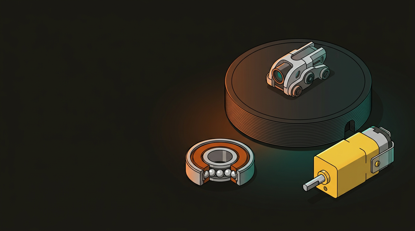
A display turntable has very few moving parts. The whole build breaks down into four elements — get these right and everything else is just finishing work.
The rotating disc that holds the model. Print flat with 3–4 perimeters for rigidity. Diameter 150–200 mm suits most desktop models.
A 608 skateboard bearing (8 mm bore, 22 mm OD) is the standard choice — cheap, available everywhere, and designed for exactly this kind of low-load rotation.
A small DC gearmotor at 3–6 RPM gives a smooth, slow rotation suited to photography or display. Stepper motors work but add unnecessary complexity.
Houses the motor and bearing, hides the wiring. Print with 20–30% infill for weight — a heavier base prevents wobble when the model is off-centre.
Platform & Bearing Design Rules
The fit between the bearing, the motor shaft, and the printed parts is where most builds succeed or fail. Print a test collar before committing to the full platform.
Bearing Seat
- 608 bearing OD is 22 mm — print the seat at 21.8 mm for a press fit
- Seat depth should match bearing width: 7 mm for a standard 608
- Print the seat in the base, not the platform, to keep mass low
Motor Shaft Coupler
- Measure your motor shaft diameter — common sizes are 3 mm and 4 mm
- Print the coupler hole 0.1 mm undersized; ream or sand to final fit
- A flat on the shaft plus a printed flat prevents slip under load
Platform Dimensions
- 150 mm diameter: suits figurines and small prints up to ~120 mm
- 200 mm diameter: handles busts, terrain tiles, and larger assemblies
- Keep platform thickness 3–4 mm — heavier than needed adds wobble
Tolerances & Clearance
- Leave 0.3 mm radial clearance between rotating and static parts
- Add a 0.5 mm lip to the platform underside to centre it on the bearing
- Print orientation: platform flat on the bed, base upright for column strength
DC Motor vs Stepper Motor
Both work — but they require completely different wiring and control setups. For a display turntable, a DC gearmotor is almost always the right choice. Steppers make sense only if you need exact angular positioning.
DC Gearmotor
- Runs directly off a 5 V USB power bank — no driver board needed
- Pre-geared models available at 1–10 RPM; no code required
- Speed adjustable with a simple PWM signal or potentiometer
- Yellow “TT motors” from hobby suppliers cost under $3 each
Stepper Motor
- Requires a driver board (A4988, DRV8825) and a microcontroller
- Enables precise step-and-hold for photography automation
- Runs warm at idle — needs active management to avoid heat in an enclosure
- Overkill for a simple display loop; worthwhile for turntable photography rigs
Build Steps
The assembly sequence matters — fitting the bearing before the motor saves rework if the press fit needs adjustment.
Print and Test the Bearing Seat
Print just the bearing seat section of the base first. Press-fit a 608 bearing — it should seat flush with moderate hand pressure. If it’s loose, reprint at −0.1 mm on the diameter before committing to the full base print.
Print the Full Base
Once the seat tolerance is confirmed, print the complete base. 20% gyroid infill gives good rigidity-to-weight ratio. Use 3 perimeters minimum around the motor mount and bearing column.
Mount the Motor
Seat the motor in its printed mount. Route the wires through the base channel before fixing — trying to thread cables after the motor is in place is awkward. A drop of superglue on the motor tabs holds it without screws.
Fit the Bearing and Coupler
Press the 608 bearing into the seat. Slide the printed shaft coupler onto the motor output shaft, then press the platform down onto the coupler’s top spigot. The bearing outer race sits in the base; the platform rotates on the inner race.
Wire and Test
For a DC gearmotor, connect motor leads to a USB-powered 5 V supply through a small slide switch. Test rotation direction — if it spins the wrong way, swap the two motor leads. Check for wobble with a model placed off-centre; shim the bearing seat if needed.
Parts & Print Settings
Everything listed here is available from a local electronics hobby shop or online — total BOM cost is typically under $10 NZD. PLA is fine for the printed parts; the loads are minimal.
Print the platform at 0.15 mm layer height for a cleaner surface — it will show up in photos. The base can be coarser at 0.2–0.3 mm. No supports required if the base is oriented with the bearing column pointing upward.
GeoSaffer runs 3D printing services across New Zealand through Plastixel — from quick one-off prints to larger production batches. If you’re prototyping a mechanism like this or need precise tolerance parts, get a quote through the link below.
Get a free quote →