
Fabrication · Product Development · Maker’s Guide
From Concept to Production:
A Maker’s Guide to Rapid Prototyping in New Zealand
The gap between a good idea and something you can manufacture is mostly a process problem, not a technology problem. This is a practical walkthrough of how product development actually works — from first sketch to production run — using the fabrication technologies available to New Zealand makers right now.
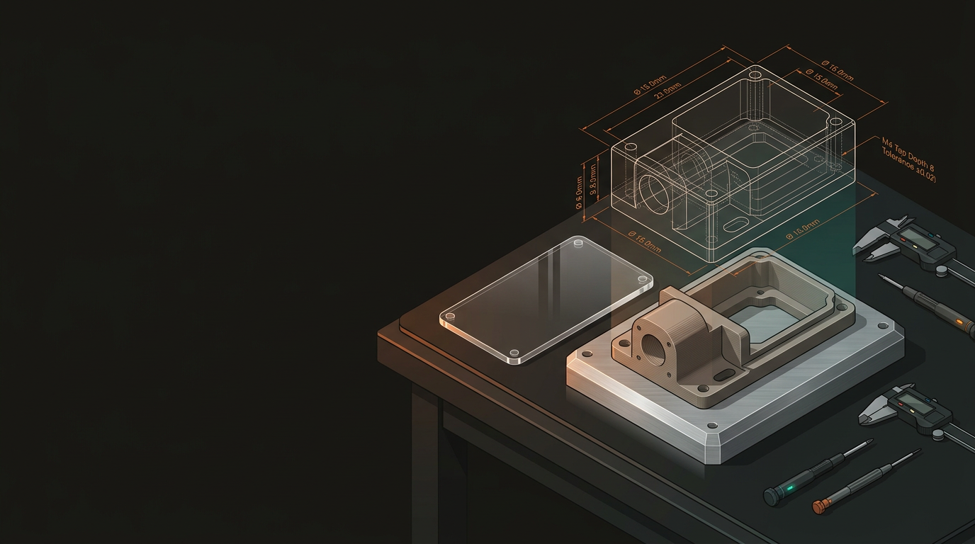
Get Your Design Into CAD
Before anything physical can be made, you need a digital model. CAD (Computer-Aided Design) software translates your concept into something fabrication machines can actually read. Most prototyping workflows use two families of file format, depending on what you’re making and how.
2D vector formats used for laser cutting and CNC routing flat profiles. Output directly from most CAD tools.
The default 3D format. Approximates curved surfaces with triangles. No unit information — always verify on export.
Retains true geometry rather than triangulating it. Far more flexible across iterations and fabrication methods.
OBJ supports colour data. 3MF is a modern replacement for STL — retains scale, units, and multi-material info.
Use STEP files where you can. When you modify designs between iterations — and you will — STEP geometry holds up far better than an STL. If CAD isn’t your background, freelance designers and many fabrication shops can work from sketches or engineering drawings to produce a workable file.
Choose the Right Technology — or Combine Them
One of the most common early mistakes is committing to a single manufacturing method when a combination would get to a better result faster. Each technology has a specific sweet spot; matching the process to the question you need answered is the core skill of rapid prototyping.
3D Printing (FDM & Resin)
- Best for complex geometries, internal cavities, fast iteration on form
- FDM: PLA, PETG, ABS, TPU — affordable and more capable than expected
- Resin: fine surface detail, small precision parts
- Parts in hand within hours of finalising a file
Laser Cutting & CNC Routing
- Laser: flat or sheet-based parts — acrylic, plywood, MDF, steel, leather
- CNC: structural timber, aluminium, HDPE, polycarbonate
- Both give more representative material properties than printed stand-ins
- CNC bridges prototyping and production for many NZ businesses
The most effective workflows mix methods. A product enclosure might use laser-cut acrylic for the shell, FDM-printed internal brackets, and a CNC-routed aluminium base plate — assembled and tested as one unit before anyone spends money on tooling. At GeoSaffer, this multi-technology approach is standard practice for complex projects.
Build to Test, Not to Impress
Early prototypes exist to answer questions, not to look finished. Trying to produce a polished result on the first iteration is expensive, slow, and tends to backfire — a rough FDM print that answers a critical question in 24 hours is worth more than a three-week, $2,000 build that reveals a flaw you could have caught on day two.
Budget upfront for multiple rounds across these four stages. The iteration is the process — it’s not a sign something’s going wrong.
Concept Prototype
Rough, fast, cheap. Validates the core idea — does the mechanism actually work? Does it fit the space it needs to occupy?
Functional Prototype
Closer to final geometry. Tests mechanisms, interfaces, and whether a real user knows how to interact with it.
Engineering Prototype
Representative materials and tolerances. Stress-tested for failure modes. Where does it break under load?
Pre-Production Sample
Effectively the final product. Used to validate manufacturing processes before committing to tooling or a production run.
Real-World Example — A Wellington Kayak Hatch System
A Wellington outdoor equipment startup needed a custom kayak hatch system. Here’s how a multi-technology approach took them from CAD to pre-production in under four months — without waiting on offshore suppliers every time a revision was needed.
Weeks 1–2: CAD & File Prep
- Hatch geometry modelled from existing boat measurements
- Files prepared for both 3D printing (latch mechanism) and laser cutting (neoprene gasket templates)
Week 3: First Iteration
- FDM prototypes printed in PETG — UV resistant and moderately flexible
- Laser-cut neoprene gaskets tested for seal quality
- Fitment issues found; latch geometry revised
Week 5: Second Iteration
- Revised mechanism passes fitment check
- CNC-routed HDPE used for the hatch body — better represents the final injection-moulded material
Weeks 8–14: Validation
- Engineering prototype handed to a group of kayakers for four weeks of real-world testing
- Minor ergonomic changes made post-test
- Pre-production samples ordered for tooling validation
Concept to pre-production in under four months. That’s not unusual when the right technologies are applied at the right stages.
Scaling from Prototype to Production
Once your design is validated, the question changes from “does it work?” to “can we make it efficiently?” Three variables drive the answer.
Volume
- Up to a few hundred units: FDM printing and CNC routing remain cost-effective
- Plastixel — GeoSaffer’s dedicated 3D printing operation — sits squarely in this gap
- Higher volumes: injection moulding, die casting, or sheet metal fabrication
Material Substitution
- Your PETG prototype may need to become glass-filled nylon or ABS for production
- Wall thicknesses and tolerances often need adjusting for the production process
- Validate material choice during the engineering prototype stage — not after tooling
Assembly Complexity
- Can the manufacturing process be simplified?
- Are there components that could be consolidated into a single part?
- Assembly steps that are fine at 10 units become expensive at 500
Tooling Confidence
- By pre-production, your geometry and material data should be validated
- Tooling investment becomes a confident decision — not an expensive guess
- Every revision avoided after tooling is significant cost saved
New Zealand’s manufacturing ecosystem is smaller than Australia or the US, which makes a capable, multi-technology partner genuinely valuable. Wrangling five separate suppliers across laser cutting, printing, CNC, electronics, and assembly adds delays and coordination overhead that quietly kills momentum.
Whether you’ve got a napkin sketch or an almost-production-ready design, GeoSaffer can look at what you’re working on, suggest the right approach for your stage and budget, and help you get something real in your hands as fast as possible. Based in Auckland, serving makers and businesses across New Zealand.
Contact GeoSaffer →