
Build a Bluetooth Low Energy Thermometerwith Arduino and the AT-09 Module
Same sensor, same sketch, same wiring — but swap the HC-05 for an AT-09 and you get a thermometer that connects to iOS and Android without manual pairing and draws less than half the current.
Classic Bluetooth (HC-05)
- 30–40 mA operating current — drains batteries faster
- Requires manual pairing in Android system settings before connecting
- Android only from third-party apps — iOS restricts the BT Classic API
- Module TX runs at 3.3 V but is 5 V tolerant on most boards
- SPP (Serial Port Profile): behaves like a virtual serial cable
BLE (AT-09 / HM-10)
- 8–15 mA operating current — significantly lower power draw
- No manual pairing required — BLE scans and connects directly
- Supported natively on iOS and Android — works with the companion app on both
- 3.3 V logic level on TX and RX — do NOT connect directly to Arduino 5 V TX without a level shifter
- Exposes the BLE UART service (Nordic NUS): TX characteristic sends data to phone, RX receives commands
For battery-powered deployments — a wireless temperature monitor in a greenhouse, server room, or outdoor enclosure — BLE makes far more sense than Classic Bluetooth. The AT-09 running at 10 mA versus the HC-05 at 35 mA is the difference between weeks and days on a small LiPo cell. The absence of any pairing step is also a practical advantage when handing a finished device to someone who isn’t technically minded.
-
1
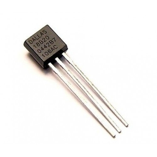
DS18B20 VCC → Arduino 5 V
The DS18B20 operates from 3.0 V to 5.5 V — connecting to the 5 V rail is the standard and most reliable option. -
2
DS18B20 GND → Arduino GND
Connect to any GND pin on the Arduino. All grounds in the circuit must share a common reference. -
3
DS18B20 DATA → Arduino Pin 2 (with 4.7 kΩ pullup)
Place the 4.7 kΩ resistor between the DATA line and the 5 V rail. Without it, the 1-Wire bus will be unreliable and readings will fail intermittently. -
4
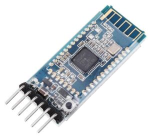
AT-09 VCC → Arduino 3.3 V
Important: the AT-09 is a 3.3 V device. Connecting VCC to the 5 V rail can damage the module. Use the dedicated 3.3 V output pin on the Arduino. -
5
AT-09 GND → Arduino GND
Tie to the same common ground as the DS18B20. -
6
AT-09 TXD → Arduino Pin 0 (RX) & AT-09 RXD → Arduino Pin 1 (TX) via voltage divider
The AT-09 TX output is 3.3 V, which the Arduino Uno RX pin (5 V tolerant) can read safely — no divider needed on that direction. However, Arduino TX outputs 5 V, which exceeds the AT-09 RX maximum. Use a simple voltage divider: a 1 kΩ resistor from Arduino Pin 1 to the AT-09 RXD pin, and a 2 kΩ resistor from that junction to GND. This brings 5 V down to approximately 3.3 V.

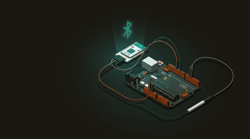
Reference wiring diagram — same layout as the HC-05 project except AT-09 VCC connects to Arduino 3.3 V (not 5 V). DS18B20 data on pin 2 with 4.7 kΩ pullup, AT-09 TXD → pin 0 (RX), AT-09 RXD ← pin 1 (TX) via 1 kΩ / 2 kΩ voltage divider.
The overall layout is essentially identical to the HC-05 project — the sole structural difference is the power rail. The HC-05 takes 5 V; the AT-09 requires 3.3 V. Get that wrong and you risk permanently damaging the BLE module.
// Include the libraries
#include <OneWire.h>
#include <DallasTemperature.h>

// Data wire goes to pin 2 on the Arduino
#define ONE_WIRE_BUS 2

// Setup a oneWire instance
OneWire oneWire(ONE_WIRE_BUS);

// Pass our oneWire reference to Dallas Temperature.
DallasTemperature sensors(&oneWire);

void setup(void)
{
 // start serial port at 9600 baud — must match AT-09 default baud
 Serial.begin(9600);
 Serial.println("Temperature Demo started");
 // Start up the sensor library
 sensors.begin();
}

void loop(void)
{
  // request temperature reading
 sensors.requestTemperatures();
 // print first sensor value
 Serial.print(sensors.getTempCByIndex(0));
 // send \r\n termination the app expects
 Serial.println("\r\n");
 // wait 1 second before next reading
 delay(1000);
}
The OneWire library handles the low-level 1-Wire bus protocol — it manages the precise timing required to communicate with the DS18B20’s 64-bit ROM and initiate temperature conversions. DallasTemperature sits on top of it and abstracts the DS18B20-specific commands: you call requestTemperatures() to trigger a conversion and getTempCByIndex(0) to read the result in Celsius from the first sensor on the bus. The serial output — a plain decimal number followed by \r\n — is forwarded by the AT-09 directly to the connected phone via the BLE UART (Nordic NUS) notify characteristic. The phone app reads each terminated line as one temperature sample.
-
1
Install libraries — in Arduino IDE: Sketch → Include Library → Manage Libraries → search
DallasTemperature→ install. The IDE will prompt to also install OneWire as a dependency; accept it. -
2
Upload the sketch — click Verify, then Upload. Wait for “Done uploading” in the status bar. If you get a serial port error, disconnect the AT-09 RX/TX wires before uploading — they share the hardware UART.
-
3
Verify via serial monitor — press Ctrl+Shift+M, set baud to 9600. You should see temperature values printing every second. If you see garbage characters, the baud rate doesn’t match.
-
4
Power the Arduino — once powered, the AT-09 LED will blink approximately once per second. This is normal — it indicates the module is advertising and waiting for a BLE connection.
-
5
Open the BLE Thermometer app on your phone — available on iOS App Store and Google Play. No system-level Bluetooth pairing is needed; BLE handles discovery entirely within the app.
-
6
Tap the device name to connect — the AT-09 LED will switch from blinking to a steady glow when a connection is established. Temperature readings will begin appearing in the app within 2 seconds.
Once your BLE thermometer is running, the free companion app handles the rest — live gauge display, 30-point graph history, and no pairing setup on either iOS or Android.
Get the BLE Thermometer App →