
Repair Circuit Board Guide Fix PCB Faults — Without Replacing the Board
Most circuit board failures come down to something visible, measurable, and fixable — a cold solder joint, a swollen capacitor, a broken trace. This guide walks you through the diagnostic process and the practical repairs, step by step, from first inspection to a working board.
Before reaching for any test equipment, spend time on a thorough visual inspection. A strong LED lamp angled across the board will reveal surface defects that disappear under flat overhead light. A loupe or USB microscope helps enormously on dense SMD boards. Around 80% of obvious faults show up here.
Capacitors, resistors, or ICs that have overheated show scorch marks or brown/black residue on the PCB surface nearby.
Electrolytic capacitor tops should be flat. Any bulging or crusty residue around the base confirms a failed cap.
Dull, grainy, or visibly cracked solder rather than a smooth, shiny, concave fillet — especially near connectors or heavy components.
Hairline cracks in copper tracks, most common near flex points, board edges, and high-vibration connectors.
Green or white residue — typically around connectors or on boards exposed to humidity. Isopropyl alcohol and a brush will clear mild cases.
Burnt holes, cracked component bodies, or mechanical impact damage. Often indicates an upstream fault caused excess current or voltage.
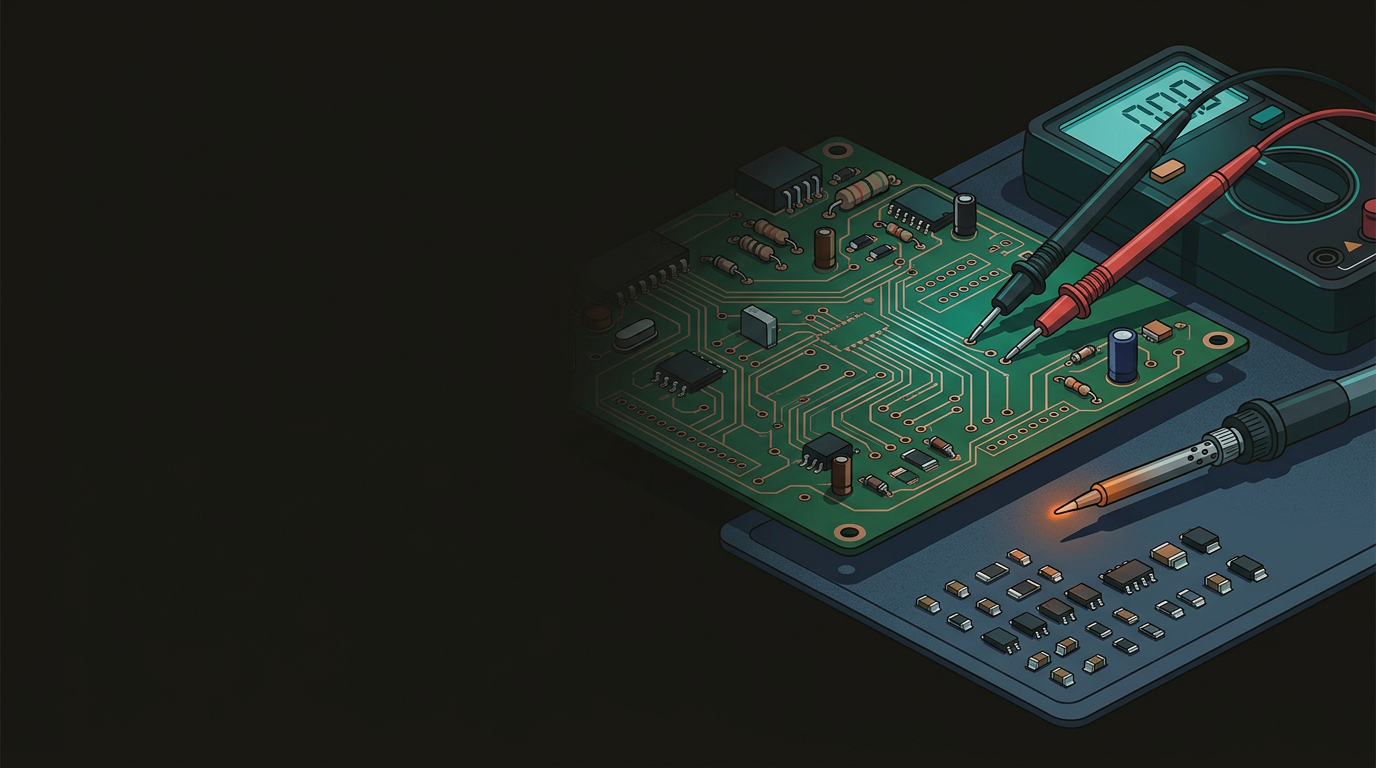
A decent digital multimeter (DMM) is the single most important tool in PCB diagnosis. Use it systematically — always check for shorts before applying power, then measure voltage rails once you’re confident it’s safe to proceed.
Checking for Short Circuits
- Set DMM to continuity (beep) or resistance mode
- One probe on a GND pin or large ground pad
- Other probe on your main voltage rail (VCC, 5 V, 12 V)
- Near-zero ohms or continuous beep = hard short to ground
- Common culprits: blown caps, shorted MOSFETs, failed voltage regulators
- Do not power up until the short is identified and removed
Measuring Voltage Rails
- Use a current-limited bench supply when first powering a suspect board
- Locate test points on the silkscreen — TP1, TP2 etc. are there to be used
- Compare readings against the schematic or service manual values
- 5 V rail reading 3.8 V → failing regulator, excess load, or marginal cap
- Completely dead rail → failed regulator, blown fuse, or upstream fault
- In-circuit resistance testing is useful but parallel paths can mislead
Cold joints and broken traces are among the most common PCB faults — and among the most satisfying to fix. A cold joint forms when solder solidifies before properly wetting the pad and component lead, usually due to movement during soldering or oxidised flux.
Apply fresh flux
Add a small amount of rosin or no-clean paste flux to the suspect joint. Fresh flux cleans oxides and ensures proper solder flow.
Reflow the joint
Touch your iron briefly to the joint — just enough to melt and reflow the solder. Remove the iron and leave undisturbed to cool. A good joint is smooth, shiny, and concave. For through-hole parts, solder should flow through the hole and form a fillet on both sides.
Expose the trace break
For a broken trace: clean the area with isopropyl alcohol, then carefully scrape back the solder mask on either side of the break to expose bare copper. Use a sharp craft knife — take your time.
Bridge the break with wire
Solder a short length of 30 AWG wire-wrap wire across the break. Tin both exposed pads first, then lay the wire and reflow. Conductive epoxy is an alternative for areas too tight for a soldering iron.
Protect the repair
Cover the wire bridge with clear nail varnish or UV-cure conformal coating. This prevents future corrosion and mechanically protects the repair.
Once you’ve identified the failed component, note the part number from the component body or schematic before you desolder anything. Sourcing is far easier with a confirmed part number. In New Zealand, Element14, RS Components, and AliExpress cover most needs.
Through-Hole Components
- Desolder using a solder sucker or desoldering braid
- Clean pads with flux and isopropyl alcohol
- Insert new component, solder cleanly
- Trim leads flush after soldering
- Inspect fillet on both sides of the board
SMD Components
- Use hot air rework or a fine-tipped iron with SMD tweezers
- Apply flux liberally before rework
- QFP/SOIC packages: drag-solder or hot air reflow
- 0201 and smaller: stereo microscope strongly recommended
- BGA requires a proper rework station — outside DIY scope
Process discipline matters as much as technical skill. These five habits will save you from the most common self-inflicted problems.
Circuit board repair rewards methodical thinking and patience — most common faults are well within reach if you approach them carefully. That said, complex faults on industrial equipment, multi-layer boards with internal damage, or anything where getting it wrong is costly are best handled by specialists. The team at GeoSaffer Ltd, based in Auckland, offers component-level PCB diagnosis and repair — not just board swaps. Get a straight answer on what’s repairable, what it’ll cost, and whether it’s worth doing.
Talk to the GeoSaffer repair team →