
Common Electronics Repair Mistakesand How to Avoid Them
Most repair disasters follow predictable patterns. Recognise them before you pick up the iron — and you save the device, the time, and often serious money.
The most expensive repair mistake is also the most avoidable: replacing components before you’ve properly diagnosed what’s actually wrong. A device that won’t power on doesn’t necessarily have a dead capacitor — it might have a hairline crack in a trace, a failed protection circuit, or a loose connector. Swap parts without finding the root cause and you’ve spent money solving the wrong problem.
Solid troubleshooting follows a strict hierarchy — and skipping any step is surgery without a diagnosis:
Look for burnt components, cracked solder joints, corroded traces, or swollen capacitors before touching anything else.
Blown fuses, tripped protection circuits, loose connectors, and broken wires account for a surprisingly large share of faults — and cost nothing to check.
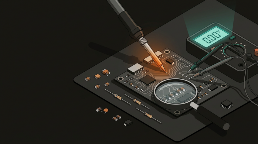
Check voltages at supply rails, test continuity across suspected joints, and measure component values in-circuit where possible. A multimeter is the diagnostic tool most often skipped.
Fault-finding means eliminating possibilities systematically. Experienced technicians spend more time on diagnostics than on the repair itself — because a correct diagnosis makes everything downstream faster.
Improper soldering technique accounts for a large proportion of botched repairs. The damage typically takes one of three forms — too much heat, too little, or the wrong materials entirely:
Too Much Heat
- Lifts PCB pads clean off the board — nearly impossible to restore
- Delaminates layers on multi-layer boards
- Destroys heat-sensitive components in the surrounding area
- Cooks IC packages, especially fine-pitch SMD chips
Cold Solder Joints
- Caused by insufficient heat or withdrawing too quickly
- Look dull and grainy instead of shiny and smooth
- May pass initial testing, then fail intermittently with thermal cycling
- If a joint looks even slightly off, reflow it — don’t leave it
Wrong Solder Type
- Plumbing solder contains acid flux — corrodes PCB traces over time
- Always use electronics-grade rosin-core solder
- Match the solder alloy to the board spec (leaded vs lead-free)
Temperature Guidelines
- 320–360°C for leaded solder; slightly higher for lead-free
- Use flux — it is not optional for clean, reliable joints
- A temperature-controlled iron is not a luxury; cheap unregulated units cause preventable damage
PCB repair demands that you correctly identify what a component is, what it does, and what the right replacement value is. Install the wrong part and you may create a fault that’s harder to diagnose than the original one.
Resistors and capacitors look identical to the naked eye. A 10Ω and a 10kΩ resistor can appear nearly the same — always read the marking under magnification and confirm with a meter.
Electrolytic capacitors installed backwards will, at best, prevent the circuit from functioning. At worst, they fail dramatically — and sometimes destructively.
A part with the correct capacitance or resistance but an insufficient voltage rating will fail under load. Always match or exceed the original rating — not just the value.
Base, collector, emitter — the pin arrangement varies between packages and manufacturers. Never assume. Check the datasheet for the exact part number you’re installing.
When there’s any doubt, cross-reference the original part number against a proper datasheet. Digi-Key, Mouser, and the component manufacturers’ own documentation are worth bookmarking before you need them.
Thermal management matters beyond the soldering process. Replacing a burnt MOSFET without establishing why it ran hot is a repair that will fail again. Look for evidence of chronic thermal stress before reassembling anything:
Browning of the PCB substrate around a component indicates it has been running hot over time — not a one-off event. The cause needs to be identified before the replacement is installed.
Heatsinks that have lost their thermal paste are conducting heat poorly. Replace thermal compound on processors and power components during every reassembly — it’s a five-minute step that prevents repeat failures.
Dust, debris, or awkward cable routing inside an enclosure can restrict airflow enough to cause repeat thermal failures. Clear and check before closing everything up.
These are symptoms, not root causes. A thermal fuse that’s opened indicates the device exceeded its safe operating temperature at some point — find out why before replacing it.
Part of being a competent repairer is recognising your limits before the board illustrates them for you. DIY repair is cost-effective and appropriate for a wide range of common faults — but some work genuinely requires specialist equipment and experience.
DIY is Generally Feasible
- Through-hole component replacement — capacitors, fuses, connectors
- Basic soldering on standard PCBs with visible, accessible joints
- Cleaning and reflowing joints with corrosion or cold joints
- Replacing modular consumables — batteries, screens, standard connectors
Seek Professional Help When
- Fine-pitch SMD (0402 and smaller, QFP/BGA) without appropriate equipment
- Multi-layer board fault with buried vias or inner-layer damage
- A prior repair attempt has shifted the fault or created a new one
- Safety implications — medical, mains-connected, or automotive
- Fault verification requires test equipment you don’t have access to
Before picking up the iron, run through these five points. Two or more “no” answers is a reasonable reason to pause and reassess.
- Have I completed a full visual inspection of the board?
- Do I have the correct tools — temperature-controlled iron, flux, quality solder, multimeter?
- Have I identified the root cause, not just the visible symptom?
- Do I have confirmed replacement components with matching value, voltage rating, and package?
- Is this repair within my current skill level and available equipment?
For Auckland businesses and individuals with damaged equipment — a failed industrial controller, a broken point-of-sale terminal, or a custom electronic assembly — GeoSaffer Ltd offers PCB-level electronics repair with the diagnostic depth to actually solve the problem rather than replace parts and hope.
Get an honest repair assessment →