How to Prepare Your CAD Files for Laser Cutting Common mistakes to avoid before you hit send
The machine isn’t usually the problem. A file that hasn’t been set up correctly will produce incorrect parts regardless of how precise the laser is — misaligned joints, blown-out details, or a full sheet wasted before anyone notices the error. Here’s what to get right before your file reaches the cutter.
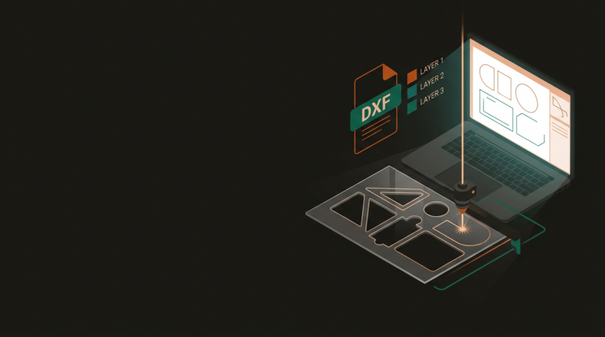
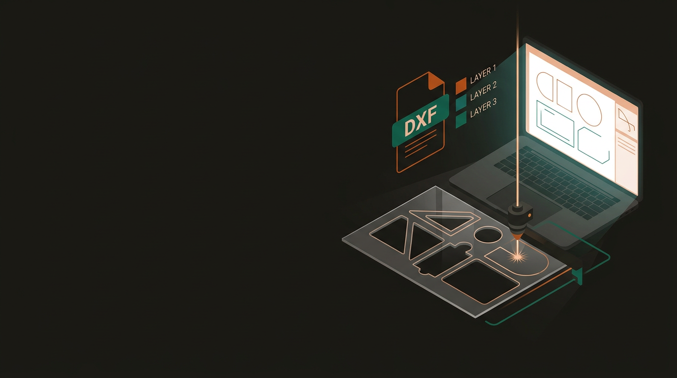
The two formats you’ll deal with most often are DXF and vector PDF. Both are workable — but they behave differently, and getting this wrong is often the first place a job falls over.
Industry standard for CNC and laser work. Exports precise geometric data directly from AutoCAD, Fusion 360, SolidWorks, and Inkscape. Use DXF R14 or 2004 for compatibility. Export as flat 2D sketch only — not a projected 3D body.
Legitimate for Illustrator or CorelDRAW work. Must be a true vector export — not a screenshot or raster image saved as PDF. Real vector paths, not pixels doing an impression of lines.
Open your PDF in Acrobat and zoom to 1000%. Crisp lines mean you’re fine. Pixelation means go back to the source file.
Laser software reads your file visually, using line colour and sometimes weight to decide what to do with each element. When everything is the same colour, an operator has to manually sort through it — which takes time and introduces room for error.
Layer Colour Convention
- Cut lines (full depth) — one colour, typically red or black
- Score lines (fold or partial cut) — separate colour
- Engrave paths (vector or raster fill) — separate again
- Consistent colour coding across every file you submit
Before You Export
- Cut line weights: 0.001 mm / hairline only
- Heavier lines read as filled shapes or engrave areas
- Delete all dimensions, annotations, construction lines
- Turn off or exclude hidden layers from the export
Kerf is the width of material the laser beam removes as it cuts — roughly 0.1–0.2 mm on 3 mm acrylic, more on thicker materials. For standalone shapes it’s negligible. For parts that connect, it’s the difference between a crisp press-fit and a sloppy joint.
If the laser removes 0.15 mm and you need a 10 mm slot in the finished piece, draw the slot at 9.85 mm. A 10 mm tab should be drawn at 10.15 mm. The direction of the offset depends on whether you’re working to an inside or outside profile. Some software handles this automatically — ask your service provider what offset they apply, or build compensation into your file and call it out clearly.
Rough Kerf Values
- 3 mm acrylic or plywood: ~0.1–0.2 mm
- 6 mm MDF: ~0.2–0.3 mm
- 1 mm steel (fibre laser): ~0.1 mm or less
- Always confirm with your service provider
Practical Steps
- Run a small sample cut before committing to a full sheet
- LightBurn can apply kerf offset automatically with the right value
- Note compensation in your brief if you’ve applied it yourself
- Test on scrap of the same material and batch
Two genuinely different processes that produce results that look nothing like each other. Choosing the wrong one for your artwork isn’t just inefficient — it produces the wrong result entirely.
Vector Engraving
- Traces the laser along design lines
- Quick — right for logos, text, linework
- Clean and precise at small scales
- Submit as AI, SVG, or DXF vector file
Raster Engraving
- Sweeps back and forth like a printer
- Handles photos, gradients, filled artwork
- Takes longer — tonal range vector can’t match
- Submit at 300 DPI minimum, 600 DPI for detail
Common error — inverted artwork: For materials like anodised aluminium or slate, the laser removes the dark surface to reveal a lighter base beneath. Artwork needs to be inverted compared to what you’d expect. If in doubt, ask your provider before the job runs, not after.
These are the things that, when skipped, account for the vast majority of rejected files and failed jobs. Keep this somewhere accessible and run through it before every submission.
DXF or vector PDF only — not a raster image or screenshot. All geometry is 2D and flat, with no 3D elements included in the export.
Cut, score, and engrave paths on separate layers or separated by colour. All cut line weights at hairline / 0.001 mm.
Duplicate lines, overlapping paths, and open paths found and removed. Dimensions, annotations, and construction geometry deleted or excluded from the export.
Kerf compensation applied — or flagged clearly in your brief. Text converted to outlines or curves before export.
Material type, thickness, and quantity specified. A reference image or PDF preview included so the operator can verify the layout makes sense before a single cut is made.
Most delays and rejected jobs at GeoSaffer trace back to the issues above — none of them are complicated, and all of them are preventable. A well-prepared file moves through production faster, comes out more accurately, and looks like what you had in mind when you designed it. If something feels uncertain before you submit, get in touch first.
Upload your files or get a quote →